The first artificial neural networks weren’t abstractions inside a computer, but actual physical systems made of whirring motors and big bundles of wire. Here I’ll describe how you can build one for yourself using SnapCircuits, a kid’s electronics kit. I’ll also muse about how to build a network that works optically using a webcam. And I’ll recount what I learned talking to the artist Ralf Baecker, who built a network using strings, levers, and lead weights.
I showed the SnapCircuits network last year to John J. Hopfield, a Princeton University physicist who pioneered neural networks in the 1980s, and he quickly got absorbed in tweaking the system to see what he could get it to do. I was a visitor at the Institute for Advanced Study and spent hours interviewing Hopfield for my forthcoming book on physics and the mind, Putting Ourselves Back in the Equation: Why Physicists Are Studying Human Consciousness and AI to Unravel the Mysteries of the Universe.
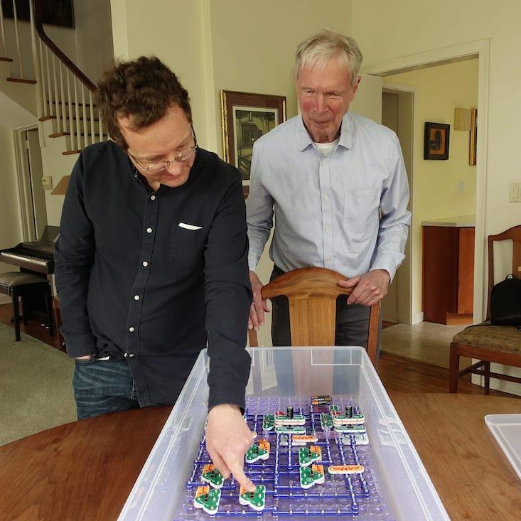
The type of network that Hopfield became famous for is a bit different from the deep networks that power image recognition and other A.I. systems today. It still consists of basic computing units—“neurons”—that are wired together, so that each responds to what the others are doing. But the neurons are not arrayed into layers: There is no dedicated input, output, or intermediate stages. Instead the network is a big tangle of signals that can loop back on themselves, forming a highly dynamic system.
You can get away with sloppy design for a three-neuron network, but will need to be more systematic with four.
Each neuron is a switch that turns on or off depending on its inputs. Starting from some initial state, the neurons jostle and readjust. A neuron might cause another to turn on, triggering a cascade of neurons to turn on or off, perhaps changing the status of the original neuron. Ideally the network settles down into a static or cycling pattern. The system thus performs a computation collectively, rather than following a step-by-step procedure as conventional computers do.
In 1981, then at Caltech, Hopfield gave a talk about his feedback network, and in the audience was a visiting scientist, John Lambe. Lambe was inspired to build the first physical instantiation, consisting of six neurons controlled by toggle switches.
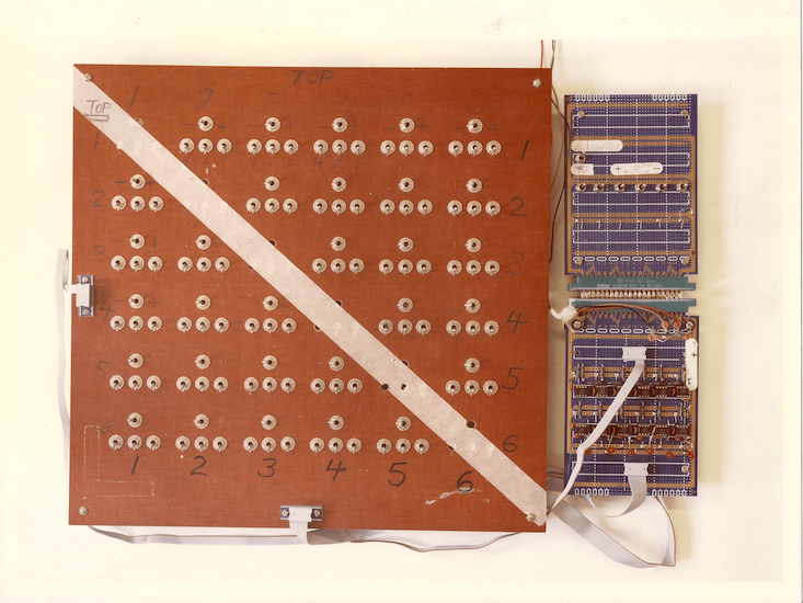
It confirmed that a network of this design stabilized rather than loop chaotically, which had been Hopfield’s main concern. Hopfield sketched the circuit in a 1984 paper.
SnapCircuits design
The SnapCircuits version has three neurons, which is the minimum number to see interesting behavior. I’ll assume you’re generally familiar with SnapCircuits and can figure out how to assemble the circuit from the diagram and photos. I’ve listed the required parts at the end of this post. They didn’t have SnapCircuits when I was a kid, and I discovered it’s harder than it looks to lay out a circuit efficiently. No doubt there are better approaches than mine, so please send me your photos.
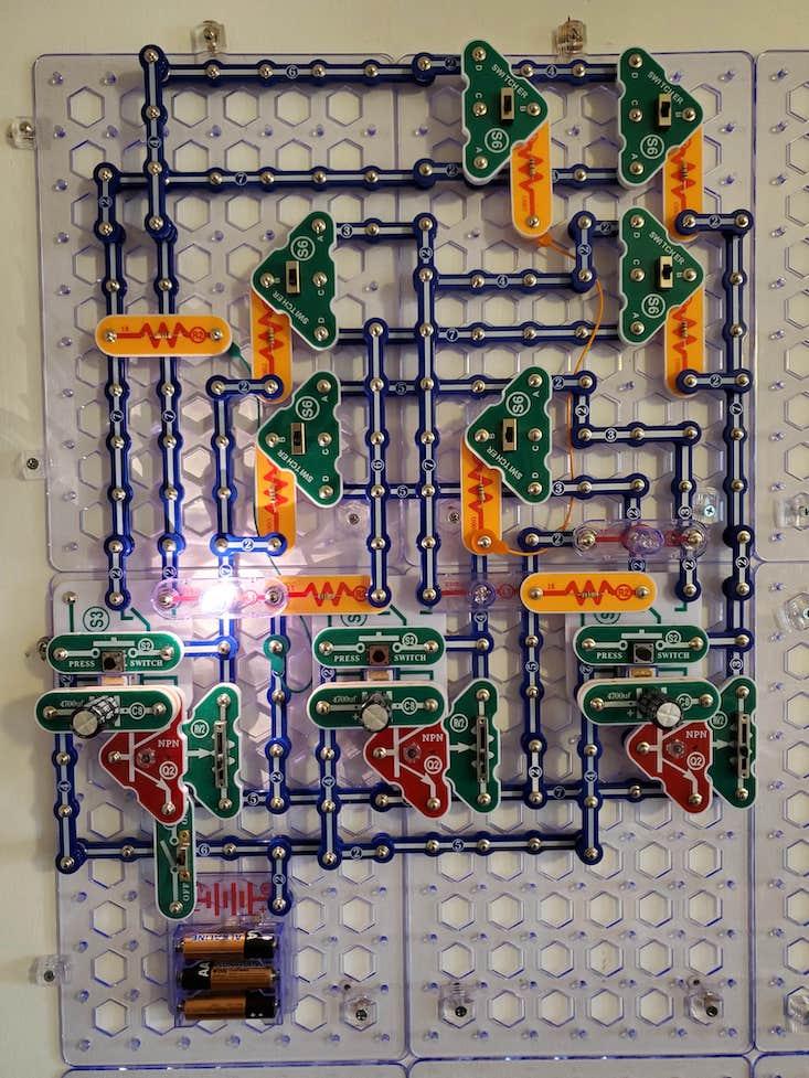
Electrical relays serve as the neurons. When their input voltage exceeds some threshold value, it switches on with a satisfying click, illuminating a lamp. One problem with relays is a memory effect: Once on, they are hard to switch off again, and vice versa. That can cause the network to seize up, as Hopfield noted in his first paper on the topic. The network as a whole can store information, but you don’t want individual neurons to do the same. To squash this problem, I pair each relay with a transistor to control its input.
A variable resistor at the transistor input lets you fine-tune the neuron threshold—its “bias”—making it easier or harder to turn on and off. The smallest variable resistor in the SnapCircuits palette has a much larger value that the resistor values I use elsewhere in the circuit, so a small change in its setting has a huge effect, and it is hard to get right. I also place a capacitor in parallel with the relay input to slow down the transitions, making it easier to watch the network evolve.
Each neuron produces both a signal and its inverse. These go to the inputs of the other neurons and are controlled by a bank of six switches. The switches are the physical form of the mathematical matrix typically used in neural-network calculations. One neuron can act either to activate or to suppress another or have no effect at all. In biological terms, their connections are either excitatory or inhibitory. In my network, the choice is made by flipping the switch between the output or its negation, with a neutral position to break the connection altogether. Notice that neurons do not connect to themselves or else you’d get the memory effect I was talking about.
Resistors at each switch allow voltages to add. The resistor values determine the strength of coupling: High resistance means low coupling. In this circuit, I’ve used equal resistor values. That’s enough to demonstrate the range of dynamics that such a simple network is capable of.
Finally, a bank of switches lets you set the initial state of the neurons, which in the argot is known as “clamping.” This is how you input data into the network. For simplicity, the switches in my circuit can clamp only to on, since the neurons are off when you first power up.
Circuit operation
To focus on just two neurons for the moment, set the input switches of the third neuron to neutral. Two neurons can be configured in three ways:
1. If you flip the first neuron’s input to excitatory and the second’s to inhibitory, you create an asymmetric network. It will run through all possible states as fast as the relays can flip. If the first neuron is on, it switches the second off through its inhibitory connection. Then the second switches the first off through its excitatory connection. Now the first will switch the second on, which switches the first back on, and the cycle repeats. The network never stabilizes.
2. If both switches are set to excitatory, each neuron turns the other on. The network settles into a stable state and stays there.
3. If both switches are set to inhibitory, you finally get something useful: a single bit of memory. The two neurons store it by their mutually reinforcing dynamics. If you press the switch to turn on the first neuron, the second will be forced off, which acts to turn on the first neuron. So, if you let go of the switch, the neurons will remain in that condition. Likewise, if you press the switch to turn off the first neuron, that will turn on the second neuron, and this condition is self-sustaining, too. Engineers refer to such an arrangement as a flip-flop.
It takes some mental gymnastics to interpret the plumb bobs as patterns in the cellular automata.
Three neurons get more interesting. You can set up a logical OR gate in which two of the neurons serve as the input values and the third as the output. Turn the 1-3 and 2-3 connections to excitatory and disable all the others. Now, neuron 3 will be on if either 1 or 2 is on, and otherwise off.
You can also do a three-neuron version of the flip-flop, in which one neuron is on and two are off, and turning a neuron on turns the others off. Just set all the switches to inhibitory.
Next, try a ring oscillator. Set the 1-2, 2-3, and 3-1 connections to inhibitory and the rest to off. The network cycles: The first neuron is on, then the third, the second, the first, and so on.
You can also experiment with two examples that computer scientist Raúl Rojas gives in Section 13.3.1 of his textbook on neural networks.
In the first, set 1-2, 2-1, 2-3, and 3-2 connections to excitatory and 1-3, and 3-1 to inhibitory. Also, turn down the neuron bias to make it ever so slightly harder to turn on the neurons. Now the neurons—no matter their initial state—will eventually all turn off and remain off. But they go through a series of intermediate states, as Rojas shows in his Figure 13.10.
Rojas’s second example is the opposite configuration. Set 1-2, 2-1, 2-3, and 3-2 connections to inhibitory and 1-3, and 3-1 to excitatory, and turn off the biases. Now the network will settle into one of two stable end points: The middle bulb is on and others off, or vice versa. These two states can be thought of as two memories that the system has stored. Other states are partial or corrupted versions that the system fills in. That is how a Hopfield network serves as an associative memory or error-correction technique.
Using Rojas’s second example, you can try training the network. A Hopfield network is trained by what biologists and machine-learning researchers call Hebbian learning: fire together, wire together. Press the clamping button to turn on the first neuron and flip the 1-3 switch to excitatory to make the third come on, too. Then press the clamping button to turn on the second bulb and flip the 1-2 and 2-3 switches to inhibitory to make the others turn off. Finally, make the switch settings symmetrical. You might need to tweak the biases.
Larger versions
If you’re ambitious, try expanding the network to four neurons. You’ll need to double the number of neuron interconnections. The exponential rise in connectivity is a general problem for hardware neural networks. “One thing you see is how rapidly the thing fills up with wires,” Hopfield told me. That is why much of our brain—the white matter—consists of nerve fibers. Also, you might need to choose different resistor values and beef up the power supply. Multi-neuron networks typically require finer control over the weighing of the interconnections. You can get away with sloppy design for a three-neuron network, but will need to be more systematic with four.
But if you do reach this level, you can implement an XOR gate, which is conceptually important. A one-layer neural network cannot implement it. The XOR function is the simplest example of a parity function, which returns 1 if the number of bits is odd and 0 if even. Parity is a deceptively simple idea that can trip up even the most advanced machine-learning systems.
For five neurons, you’ll probably have to switch from SnapCircuits to breadboarding. A five-neuron network can have two attractor states that provide a simple associative memory. Other five-neuron networks can be found here and here.
As for six neurons, Hopfield and his co-author David Tank give an example of what you could do with them in a Scientific American article.
Another interesting direction is to add an element of randomness. In a Hopfield network, the dynamics is deterministic: A neuron’s state is determined entirely by its interconnections. In a more advanced network, a neuron might spontaneously flip. In SnapCircuits, you might try adding a switch and letting a human press it at will. Then the network will not settle into a single state, and neurons will continue to flip on and off. But the network as a whole still settles into thermal equilibrium, again showing the power of collective dynamics.
Webcam version
Another early physical network was optical. Imagine pointing a camera at the screen of the camera’s own image, creating a feedback loop. If the image gets brighter, the camera picks that up, the screen gets even brighter, and so on, until it maxes out. If the screen darkens, that loops around, too, until it becomes pitch black. In this way, feedback creates two stable states, which can serve as a neuron.
To create multiple neurons, use a cardboard mask to divide the screen into multiple areas. Judicious cutting of the cardboard mask can make each neuron sensitive to the others. If you get it right, the dynamics will be the same as in the SnapCircuits network.
At any rate, that’s the idea. I tried to do this using two phones running a remote webcam app known as Alfred. I pointed the camera of one at the screen of the other. But the masking and alignment are very tricky. Hopfield has experimented with this, too, but neither he nor I got it to work.

Please let me know if you succeed.
Mechanical version
The artist Ralf Baecker has created a remarkable mechanical neural-network model.
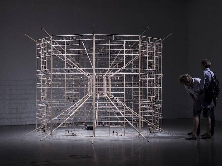
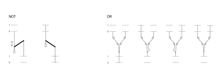
The position of a plumb bob represents a bit: up for 1, down for 0. A lever is a NOT gate: When one end is down, the other is up. A plumb bob hanging from several strings gives you an OR gate: Pulling on any of the strings will lift the bob. Everything else can be built out of those two gates.
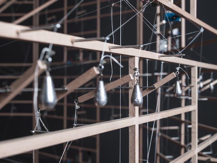
The weights in Baecker’s network weights are not adjustable. The network runs a fixed program: a cellular automata, which is a kind of simulated universe governed by its own laws of physics. The network executes cellular-automata rule 110, which is found on the cover of Stephen Wolfram’s book A New Kind of Science. Rule 110 is a one-dimensional version of the better-known Game of Life cellular automata and can create a self-contained universe filled with gliders—moving structures that can transmit information and perform computational operations.
Baecker’s system is way too small to show gliders, alas, and doesn’t directly “show” anything, anyway—it takes some mental gymnastics to interpret the plumb bobs as patterns in the cellular automata. The installation implements nine cells and shows three time steps at any moment. Each cell is connected to itself and its two neighbors in the previous timestep.
To update a cell requires eight NOT operations and four ORs. In between each time step is a switch and servo motor, which introduces a three-second delay to give the mechanical components time to settle. The nine cells are arrayed around the circumference, and the three timesteps are vertical. The bottom is fed back to the top, so the system can run continuously. Baecker told me the system will run a couple of hours before friction wears it down and it has to be restarted.
“For me the focus is on the process and not so much on the actual results,” Becker said. “The mechanical parts make some nice ‘click’ sound. I usually use my ears to check if the machine runs well. The clicks travel in certain circle and patterns around the machine, like crickets.” ![]()
SnapCircuit circuit diagram and parts list
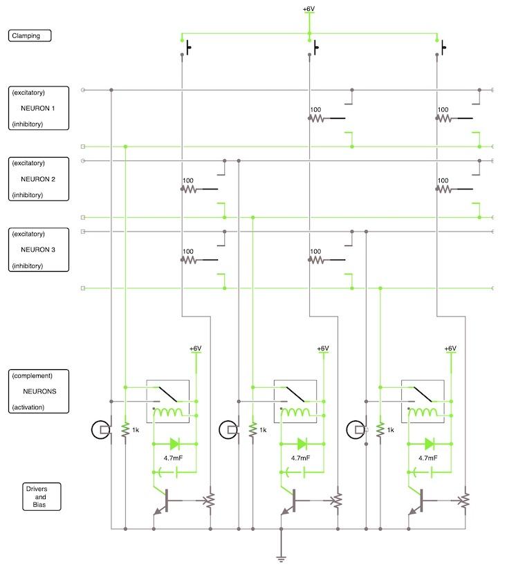
For each neuron, you will need:
Q2 transistor
S3 relay
S2 switch
RV2 variable resistor 10 kΩ
D3 diode
C8 capacitor 4700 µF
L1 lamp
R2 resistor 1kΩ
The diode is hidden in the photographs above, but is placed under the capacitor to prevent voltage spikes—a so-called flyback diode.
For the bank of switches, you will need two of each of the following for two neurons, six for three, and 12 for four:
S6 switch
R1 resistor 100Ω
Finally, you will also need:
several base grids: I needed four for a three-neuron network
power supply and switch
lots and lots of connection strips and wires


